Rangkaian ini dapat mendeteksi jarak antara bemper mobil dengan dinding atau apa saja yang menghalangi kendaraan baik yang berada di depannya maupun dibelakang mobil. Jarak bisa diketahui dari kombinasi antara LED D5 dan D7. Misal bemper berada pada jarak 25cm atau kurang maka D7 akan menyala, jarak berada pada 20cm maka D7dan D6 akan menyala, dan jarak pada 5cm makanD7, D6, dan D5 akan menyala semua. Pada jarak kurang dari 25cm tidak ada Lampu Led yang menyala, ini mengindikasikan masih pada jarak aman atau masih jauh dengan benda atau rintangan yang menghalanginya.
 |
| Skema rangkaian transmitter sensor parkir mobil |
 |
| Skema rangkaian Receiver sensor parkir mobil |
- D1 & D2 must be mounted close (~2cm)
- D1 can be a general purpose IR LED.
- D2 can be general purpose IR photo diode with sun filter.
- Transmitter as well as receiver can be powered from the car battery.
- For proper working of the circuit, some trial and error is needed with the position of D1 and D2 on the dash board.
Two ICs are used in the circuit. The IC1 (NE555) is wired as an astable multivibrator for driving the IR Diode D1 to emit IR pulses. The operating frequency of the transmitter is set to be 120Hz.The IR pulses transmitted by D1 will be reflected by the obstacle and received by the D2 (IR photo diode).The received signal will be amplified by IC2a.The peak of the amplified signal will be detected by the diode D4 and capacitor C4.R5 and R6 compensates the forward voltage drop of D4.The output voltage of the peak detector will be proportional to the distance between car’s bumper and obstacle. The output of peak detector is given to the inputs of the other three comparators IC2b,IC2c and IC2d inside the IC2(LM324).The comparators switch the status LEDs according to the input voltage their inverting inputs and reference voltages at their non inverting inputs. Resistances R7 to R10 are used to set the reference voltages for the comparators.
Lay out IC LM324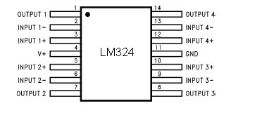
Features
Internally frequency compensated for unity gain
Large DC voltage gain 100 dB
Wide bandwidth (unity gain) 1 MHz (temperature compensated)
Wide power supply range:Single supply 3V to 32V or dual supplies ±1.5V to ±16V
Very low supply current drain (700 μA)—essentially
independent of supply voltage
Low input biasing current 45 nA (temperature compensated)
Low input offset voltage 2 mV and offset current: 5 nA
Input common-mode voltage range includes ground
Differential input voltage range equal to the power supply voltage
Large output voltage swing 0V to V+ − 1.5V.
