Anda mempunyai perangkat audio dengan speaker mahal? tentunya sayang kan kalau rusak atau jebol gara2 suaranya terlalu keras atau menerima tegangan yang terlalu tinggi. Anda baru berfikir butuh rangkaian pengaman speaker tat kala sudah mengalami kerusakan. Nah sebelum mengalami kecelakaan ada baiknya anda Sedia payung sebelum hujan. Maksudnya kita bikin Rangkaian pengaman untuk Speaker kesayangan kita.
Why to have The speaker protection circuit? How do the speaker protection circuit can prevent the speakers? This may be questions understand of somebody, and if you have not yet received a satisfactory answer, here is the answer.
For the power amplifier circuit in the new version, usually popular to build by the direct coupling circuit, from the the amplifier circuit to the speakers directly, or as also known as the OCL amplifier circuit. Which this pattern are both positive and negative power supply circuit, or what I call is the three wire power.
Features of this circuit has the advantage is that the frequency response is better than any other circuit. But it has the disadvantage that when the circuit is damages. In any case, it may be has a DC voltage positive or negative that the higher like the power supply, output to Immediately the speakers.
With this voltage, will make coil of the speaker is burned and lack of eventually, so if we do not want to the speaker is usually the most expensive audio system, need to damaged. We need to do is cut this voltage not go out the speaker. We call this circuit. Speaker protection circuit. As shown belo
Rangkaian Pengaman Speaker :
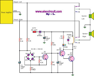
Working of circuit
As shown in this circuit, we take a some signal from the speaker enter through the resistors R1, R2 into the protection speakers section, By reducing the signal strength lower down, then after the capacitor C1 serves to bypass this signal to ground.
However, if the dc voltage to either positive or negative, whatever this voltage is passed through the bridge diode circuit immediately, by they will be setting voltage input is positive or negative to the positive voltage to the base pin of Q1 doing the Q1 work.
When the Q1 working, will make the collector voltage low down, the bias voltage at base pin of Q2 will also lower down, making The Q2,Q3 stop run therefore not have current pass through the relay RY1, so it will be cut off the signal of power amplifier without to output speaker at once. The speakers will safe from the dc power.
To be used.
1. to connect the ground wire from the amplifier to ground of the protection speaker.
2. to connect the signal output from the the amplifier to the speakers,we connected it to the IN of the protection speaker to both the left and right.
3. to connect the OUT signal from the speaker to the positive terminal of the protection speaker.
To build and test circuit.
1.To produce the correct devices in the PCB.
2.Check the soldering is done at every point.
3.Test the functionality of circuit. By connected power supply circuit. And see the LED to stick and hear a click with the relay working.
4.Experiments, connected DC voltage at the IN of the anti-speakers, the LED will extinguish along with the relay will stop immediately. If you do not follow this. Show that a failure occurs. Make sure to found before it is available.
Source: http://www.eleccircuit.com
Tag: Rangkaian Pengaman Speaker, Speaker Protection Circuit, Rangkaian Pengaman speaker, Skema Pengaman Speaker
